There's a failure mode in automotive drivetrain components that takes two to three years to appear and another six months to trace back to its origin. A helical gear shaft — normalized, carburized, ground — passes every inspection at goods-in. Dimensional tolerances are within IT6. Hardness checks at 60 HRC on the tooth flank, 30 HRC at the core. Magnetic particle inspection clean. The shaft runs fine for 18 months and then starts showing fatigue cracks initiating at the tooth root fillet, not at the expected stress concentration geometry but offset slightly — as if the failure is running along a path that the design stress analysis didn't predict. Strip the shaft back in a failure investigation, section and etch it, and what the metallographic examination shows is machining damage at the case-core interface: a decarburized remnant layer where the turning operation cut through the forging's surface skin but didn't remove it completely, combined with a grinding burn white layer 8–12 µm thick at the tooth flank surface. The grain flow that forging built into that tooth root fillet is intact below. Above it, two compounding machining errors have created a crack initiation site that the design model never modelled because it assumed the machining was done correctly.
This is the failure forging machining suppliers get blamed for when it surfaces in warranty data — and it is entirely preventable when the secondary operations are designed around preserving the mechanical advantage forging creates, not just achieving the dimensional callouts on the drawing.
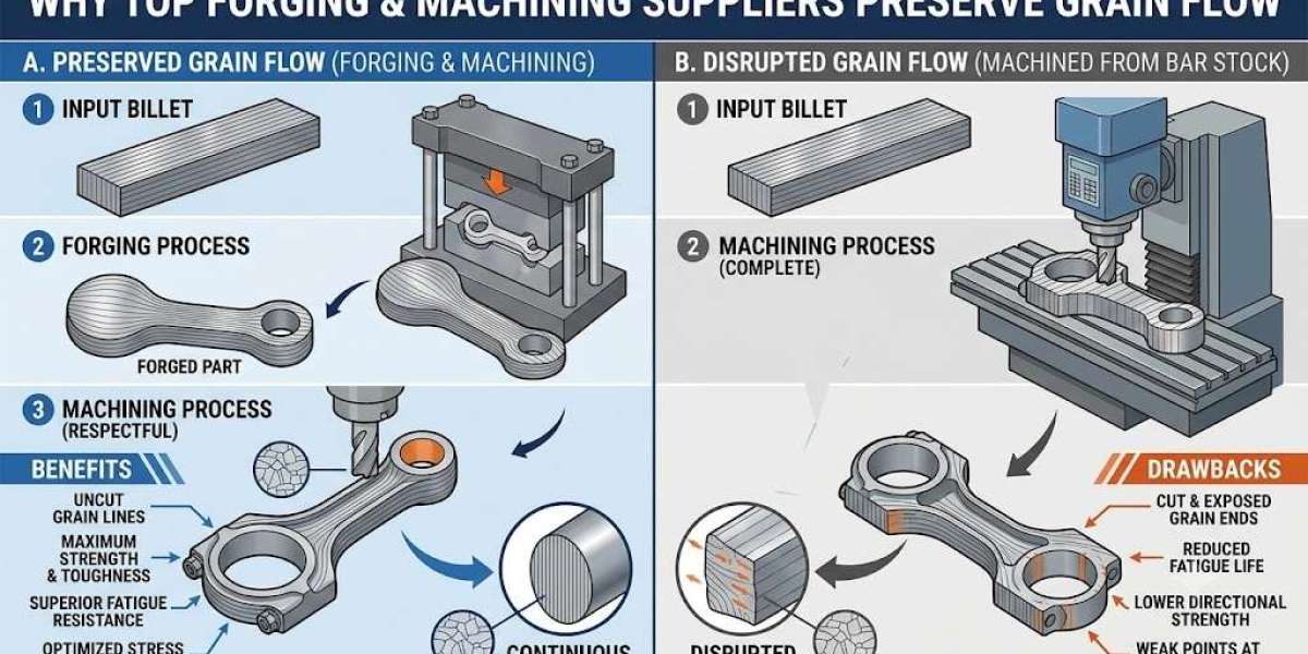
What Grain Flow Is and Why Machining Can Undo It
Forging builds directional grain flow into a component by compressing solid billet at 1,100–1,250°C inside a closed die, forcing the metal's crystalline structure to align with the geometry of the part. In a gear blank, this means the grain runs continuously through the tooth root fillet, around the hub bore radius, and along the face transitions — following the shape rather than cutting across it. In a cross shaft for a differential, the grain aligns axially through the shaft body and transitions into the flange boss in a continuous curve. This continuity is what produces the 20–30% fatigue strength advantage over machined-from-bar stock that controlled testing consistently demonstrates — the grain boundaries at the highest stress zones are oriented to resist crack propagation rather than lie perpendicular to it.
Machining interrupts that advantage in two specific ways that are distinct from each other and require different controls to prevent. The first is decarburization remnant — the 0.3–0.8mm surface layer of the as-forged component where carbon has migrated outward during heating, leaving a softer, carbon-depleted skin. If the rough turning pass doesn't remove this layer in its entirety before case hardening, the decarburized zone carburizes from a lower baseline carbon content than the bulk material and produces a shallower effective case depth at the surface than the nominal carburizing cycle predicts. The second is grinding burn — the white layer of untempered martensite created when grinding heat exceeds the tempering temperature at the wheel-workpiece interface, typically forming a 5–20 µm layer with hardness above 900 HV and essentially zero ductility. Neither defect shows on incoming hardness testing. Both initiate fatigue cracks.
Forging machining suppliers who understand grain flow preservation design their machining sequences so that the rough turning stage takes cuts deep enough to clear the decarburized skin before the part goes to heat treatment, and the finish grinding parameters stay inside the thermal damage threshold on every piece, not just on the process capability study sample.
The Machining Sequence That Preserves What Forging Built
The sequence that preserves grain flow advantage isn't complicated to describe — it's difficult to execute consistently at production volumes, which is why many forging machining suppliers achieve it on first-off samples and drift from it over the course of a production run.
Rough turning is the critical stage for decarburization removal. The decarburized skin depth on hot-forged medium carbon steel in the 1045–4340 range runs 0.3–0.8mm depending on forging temperature, furnace atmosphere, and time in die. The rough turning pass must remove this skin completely across every surface going to heat treatment, which means the minimum depth of cut must account for the forging's dimensional variation — if the as-forged tolerance allows ±0.6mm wall thickness variation, the nominal cut depth must be set at decarburization depth plus the upper dimensional bound, not the average. A nominal 1.0mm cut on a part with ±0.6mm variation delivers as little as 0.4mm actual cut at the high side — not enough to clear a 0.5mm decarburized skin before the part goes to carburizing.
Semi-finish turning establishes the dimensional datums that all downstream operations reference. For a helical gear shaft running at 5,500 RPM in a transmission application, bore concentricity established at semi-finish must hold within 0.025mm TIR to prevent bearing preload asymmetry that gear mesh forces amplify over service life. Concentricity errors within drawing tolerance individually can stack with pitch line runout from hobbing to produce a combined transmission error that causes noise at specific speed-load combinations — the complaint that generates a warranty claim described as "gear whine at 80 km/h under light load" that takes two months to trace back to datum setting at semi-finish.
Finish grinding on hardened components — typically in the 58–62 HRC range for case-hardened transmission parts — is where thermal damage risk peaks. The parameters that control grinding burn are specific and interrelated: wheel speed (typically 28–33 m/s for vitrified-bond aluminium oxide on case-hardened steel), workpiece speed (the inverse relationship with wheel speed that governs chip thickness and heat generation), infeed rate (0.005–0.015 mm per pass for finish grinding on hardened surfaces), and coolant delivery rate and direction. The nital etch test — swabbing the ground surface with 2–4% nitric acid in ethanol and examining the colour pattern under adequate lighting — is the production verification method for grinding burn. Dark etching indicates re-hardened martensite. Light etching indicates over-tempered zones. Both are thermal damage signatures. Forging machining suppliers who specify nital etch inspection in their control plans at the grinding stage, rather than relying on Rockwell spot checks at the end of the line, are treating grinding burn as the process risk it is rather than the documentation afterthought it becomes after a warranty campaign.
Why Fixture Design at Machining Is a Grain Flow Question
The connection between workholding fixture design and grain flow preservation is rarely discussed outside a detailed DFM review. Clamping force applied incorrectly during CNC turning can induce residual stress at the jaw contact points — on a thin-walled gear blank, three-jaw chuck clamping can oval the bore by 0.01–0.02mm, within drawing tolerance on the bore itself, but manifesting as a concentricity error on unclamping because springback is not uniform around the circumference. That ovalisation forces a compensating pass at finish boring that removes more material from the reduced-wall lobe points — exactly where the forging grain runs closest to the bore surface.
Mandrel fixturing during OD turning and grinding is the correct approach for thin-walled gear blanks where the wall-to-bore ratio drops below 1.5:1. A hydraulic expanding mandrel at 150–200 bar distributes clamping force uniformly around the bore, holding ovalisation below 0.003mm and allowing the OD grinding pass to run without asymmetric residual stress. The tooling cost is higher than a standard three-jaw setup, but the alternative is a part that is within specification in the fixture and marginally out on release — a drawing escape the assembly process or the field catch, not the machining operation.
Tolerance, Capability, And What the Numbers Mean in Practice
The distinction between a forging machining supplier who can produce a correct part and one who produces correct parts consistently at volume is measured in Cpk, and the IATF 16949 minimum of 1.67 on special characteristics is not a bureaucratic threshold — it is the statistical boundary below which the process cannot guarantee conformance at production rates above roughly 10,000 pieces per year. A Cpk of 1.67 on a journal diameter tolerance of ±0.010mm means process standard deviation below 0.002mm — achievable on a properly calibrated CNC grinding machine with in-process air gauging and thermal compensation active. A process running Cpk 1.33 on the same feature has a standard deviation of 0.0025mm and a predicted defect rate of approximately 64 parts per million at steady state — at 15,000 pieces per month, that's roughly one defective journal diameter per week slipping through in-process inspection into an assembly that won't fail the OEM's end-of-line test but will present a bearing fit problem in field service.
The table below illustrates how the tolerance progression through a typical forging machining suppliers production sequence maps against the Cpk requirement at each stage, using a transmission counter shaft as the reference component.
Machining Stage | Feature | Typical Tolerance | Minimum Cpk | Control Method |
Rough Turning | Stock removal depth | ±0.5mm from nominal | 1.33 | Tool offset check, first-off inspection |
Semi-Finish Turning | Bore concentricity | 0.025mm TIR | 1.67 | CMM, 100% in-process air gauge |
Gear Hobbing | Pitch line runout | 0.020mm per IS 2535 | 1.67 | Gear measuring machine, SPC chart |
CNC Cylindrical Grinding | Journal diameter | ±0.008mm (IT6) | 1.67 | In-process air gauge, post-process CMM |
Nital Etch Inspection | Grinding burn | Pass/fail | 100% | Visual examination, trained operator |
Final CMM Check | GD&T stack | Per drawing callout | 1.67 | CMM report, PPAP dimensional results |
Sendura Forge Pvt. Ltd., certified to IATF 16949:2016 and ISO 9001:2015, runs integrated forging machining suppliers operations from belt-drop hammer forging through CNC machining and inspection across a product range exceeding 700 part numbers — balancing shafts, helical gear and shaft assemblies, gear blanks, cross shafts, ring gear carriers, coupling flanges, and counter shafts — serving customers including DANA, Mahindra, Eaton, WABCO, Escorts, New Holland, TAFE, and Bonfiglioli, with in-house QA/QC including the full CMM, hardness, and metallographic inspection capability that grain flow preservation requires.
Conclusion
The reason the best forging machining suppliers focus on grain flow preservation during secondary operations isn't philosophical — it's because the failure modes that appear when they don't are expensive, delayed, and difficult to attribute. A decarburization remnant that survives rough turning doesn't appear in dimensional inspection, hardness testing, or MPI. A grinding burn white layer doesn't register on a Rockwell check. Both show up in fatigue crack initiation data two years into a warranty period, in a field failure investigation that works backward through heat treatment records, machining logs, and incoming material certification before it finds the actual cause.
Forging machining suppliers who design their sequences around preventing those failures — decarburization removal built into the rough turning depth-of-cut specification, grinding parameters monitored against thermal damage thresholds, nital etch inspection in the control plan at every ground surface — are not doing extra work. They are doing the work that the application's fatigue life requirement actually demands, at the stage where it costs the least to get right. Suppliers who discover the same requirement at the warranty campaign stage are doing the same work at ten times the cost, under considerably worse conditions.